Seal Support Systems 2: Buffer and Barrier Plans
Seal Support Systems: Buffer & Barrier Plans
Phil Daniels, Regional Field Engineer
Recap
Welcome back to blog post #2 in the Seal Support Systems series! The first blog post in the series explored the various types of Seal Support Systems, the very common flush-type plans, and using API 682 for proper selection. Seal Support Systems help ensure peak performance of mechanical seals in process pumps, and different types of plans are required for different pump applications. This post focuses on Buffer and Barrier Plans.
Buffer and Barrier Plans
Buffer and Barrier Plans use a circulating liquid or gas as a buffer or barrier between the process fluid and the atmosphere. These plans are often associated with the use of a secondary mechanical seal, further reducing the risk of process fluid to the atmosphere. This use of a dual seal means that a seal plan may require the combination of a flush plan for the primary seal, as well as a buffer or barrier plan for the secondary seal.
The primary difference between a Buffer and Barrier Plan is whether the Seal Support System is pressurized and therefore whether leakage over the seal is inboard or outboard. For a Buffer Plan, the seal support system provides an unpressurized fluid to the seal chamber which acts as a buffer between the process and the atmosphere. When process fluid leaks across the mechanical seal, it will be "captured" within the buffer fluid and is prevented from exiting the seal chamber. Conversely, a Barrier Plan provides pressurized fluid to the seal chamber, creating a more direct "barrier" to the leakage of the process fluid. This is accomplished by pressurizing the barrier fluid above the seal chamber pressure. In short, Buffer Plans are normally used where process fluid leakage should be minimized and contained, whereas Barrier Plans are used when no leakage to atmosphere can be tolerated1.
Types and Variations
Within the categories of Buffer and Barrier Plans, some variations are available that provide benefits to certain applications. One of the most common plans is Plan 52, which is an external seal pot containing an unpressurized seal fluid. An example of a Plan 52 is shown in Figure 1 below.
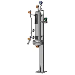
Figure 1. Plan 52 seal plan assembly, buffer fluid seal pot.
Similar to the Plan 52 for Buffer Plans is the Plan 53 for Barrier Applications. Plan 53 is available in three common configurations which utilize different methods to achieve pressurization. Plan 53A uses a seal pot like Plan 52, however the seal pot is pressurized using a blanket of nitrogen gas. Alternatively, Plan 53B uses a pre-pressurized bladder accumulator, which has the benefit over Plan 53A of not allowing gas absorption into the barrier fluid. Plan 53C uses a third type of pressurization source, a piston accumulator. This unique arrangement is driven by a sensing line from the seal chamber, allowing for a constant pressure differential to be maintained between the seal chamber and the barrier fluid. An example of a Plan 53B is shown in Figure 2 below.
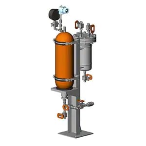
Figure 2. Plan 53B seal plan assembly, barrier fluid arrangement utilizing a bladder accumulator.
Plans 52 and 53 both rely on positive circulation within the circuit using a pumping ring. In certain cases, a larger, external Seal Support System is required that makes use of a pump and an external reservoir. This is demonstrated by Plan 54 (pressurized) and Plan 55 (unpressurized), which also make use of other complementary components such as filters, coolers, and other items. An example of a Plan 54 is shown in Figure 3 below.
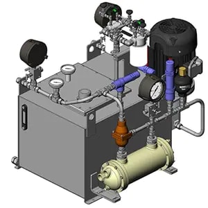
Figure 3. Plan 54 seal plan assembly, barrier fluid arrangement pressurized by external skid system.
Finally, Buffer and Barrier Plans may also make use of gases. Plan 72 supplies a buffer gas, typically nitrogen, from an external source to the seal chamber. These plans often include the use of filters, pressure regulators, and flowmeters to ensure the gas is in the appropriate condition for the mechanical seal. Alternatively, Plan 74 supplies barrier gas, which is pressurized above the seal chamber pressure.
It is important to note that Gas Seal Support Systems are only intended to be used with mechanical seals that are designed for use with gas seal fluids. Additionally, it is common to pair the Plan 72 with an associated leakage collection Plan 76, which collects the gas mixture exiting the seal chamber. An example of a Plan 74 is shown in Figure 4 below.
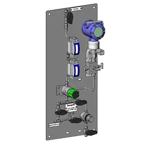
Figure 4. Plan 74 seal plan assembly, barrier gas panel.
Best Practices & Options
In addition to the various seal plan arrangements used for buffer and barrier seal applications, there are further best practices and options that may be employed. For example, a Plan 53 may use a water or air cooler to ensure heat dissipation from the seal fluid circuit. Other common best practices are recommended in the 4th edition of API 682, including the use of block and bleed valves with measurement devices and the use of pressure, temperature, and level transmitters and switches1. These best practices and options help to ensure proper mechanical seal operation, reliability, and safety.
Our global team of Field Engineers are also available to help you achieve safe and reliable Seal Support Systems through our Onsite and Virtual Fluid System Evaluation and Advisory Services.
For more information, please reach out to us below:
subscribe to the swage talks blog
1. API Standard 682, Fourth Edition, 2014 "Shaft Sealing Systems for Centrifugal and Rotary Pumps," American Petroleum Institute, Washington, D.C.